When designing a printed circuit board (PCB), the smallest components often carry the most weight in terms of performance. Surface mount resistors (SMD resistors) are no exception.
While they may seem insignificant at first glance, the size, placement, and thermal management of these tiny components can make or break the functionality of your circuit. This guide will dive into how optimizing your PCB layout for SMD resistors can vastly improve your design’s efficiency, reliability, and manufacturability.

Decoding SMD Resistor Sizes: Why Size Really Does Matter
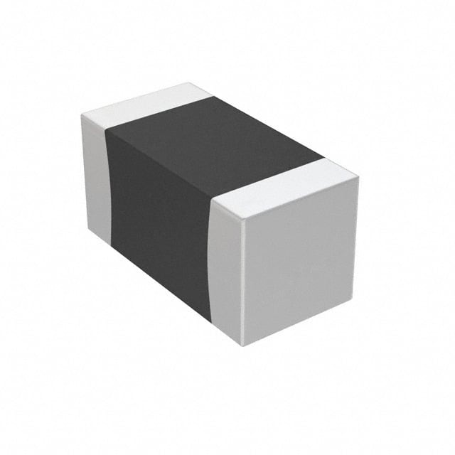
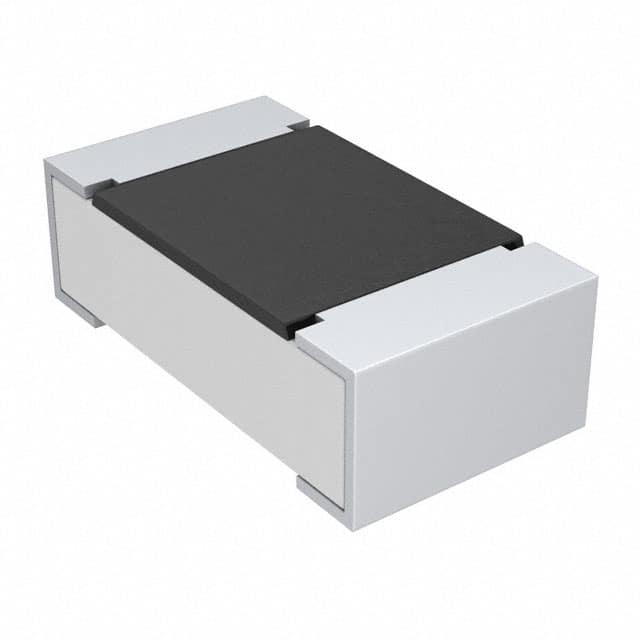
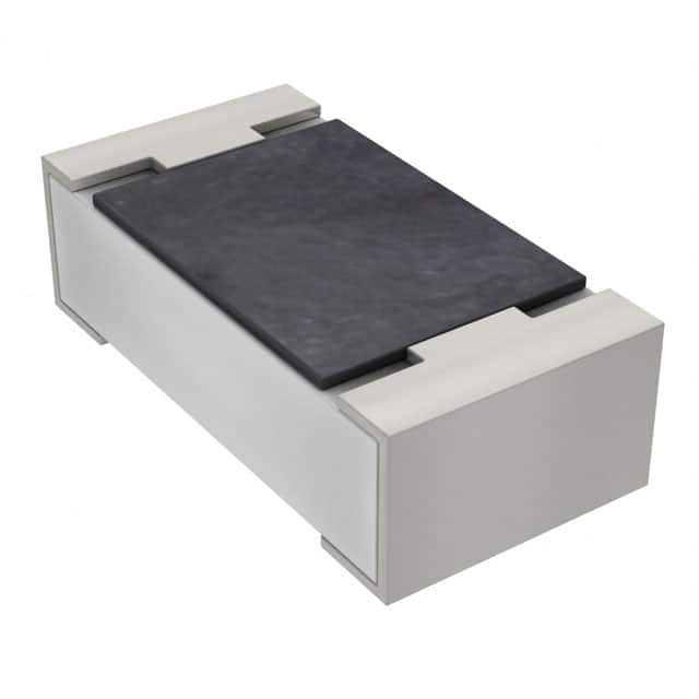
SMD resistors come in various sizes, and just like choosing the right pair of shoes for a race, picking the right size ensures your design fits its needs. Here are some common sizes and how each one plays its part:
- 0402: The tiniest of the bunch, the 0402 resistors are best for dense, compact designs, such as wearable devices or miniaturized gadgets. Despite their size, they are not ideal for high-power applications due to limited power dissipation capacity.
- 0603: A slight step up from 0402, the 0603 provides more flexibility in terms of handling power while maintaining compactness. This size strikes a good balance between performance and space efficiency, often found in smartphones and portable electronics.
- 0805: Popular in consumer electronics, 0805 resistors can handle more power without occupying much space. Their larger size makes them easier to assemble and solder compared to their smaller counterparts.
- 1206: For applications that demand higher power handling, the 1206 is your go-to. It’s also much easier to handle during the assembly process, making it a common choice for power supply circuits or automotive applications.
When deciding on the right size, think of it like picking the right tool for the job. The size impacts not just the physical footprint but also the resistor’s power rating, heat tolerance, and the ease with which it can be assembled.
also read: Potentiometer vs. Variable Resistor: Practical Insights Applications
Perfecting Your PCB Layout for Surface Mount Resistors

When it comes to surface mount resistors, your PCB layout can make the difference between a functional, reliable design and one riddled with issues like heat buildup or signal interference. Here are some best practices that will ensure you’re not just squeezing components into place but strategically positioning them for peak performance.
Resistor Placement: The Subtle Art of Positioning
Just like arranging furniture in a room, the placement of your resistors on the PCB matters. Avoid overcrowding components, as this could create thermal hotspots or limit airflow. Also, resistors should be placed as close to the related components (e.g., transistors or ICs) as possible. Minimizing trace lengths reduces parasitic inductance, improving overall circuit performance. It’s also important to consider heat-sensitive components—keep your resistors away from those that can’t handle too much temperature.
Trace Width: Finding the Right Balance
Think of PCB traces as the highways of your circuit. The wider the highway, the more traffic (current) it can handle. When routing traces near your SMD resistors, ensure they are wide enough to handle the current but narrow enough to save space. Oversized traces waste valuable real estate, while undersized traces could overheat and fail. Use the right tools to calculate trace widths based on the current your circuit is handling—there’s no need to guess.
Thermal Management: Keeping Your Resistors Cool
Resistors generate heat, and if that heat isn’t managed, your circuit could overheat, leading to failures. For higher-power resistors, consider using thermal vias to channel heat away from critical areas. Adding copper pours or ground planes beneath the resistors can also help distribute the heat more evenly. It’s a little like giving your resistors a personal cooling system.
How Resistor Size Affects the Assembly Process
When you’re designing with SMD resistors, size is more than just an aesthetic choice—it directly impacts how your board will be assembled.
Automated Assembly: Small resistor sizes like 0402 or 0603 might seem ideal for tight designs, but they pose challenges for automated pick-and-place machines. These tiny components can be tricky to position accurately, leading to defects. Larger sizes, such as 0805 or 1206, are easier for machines to handle, ensuring faster and more reliable assembly.
Soldering and Reliability: The smaller the resistor, the more challenging it becomes to solder properly. Smaller resistors may have less surface area for the solder joint, making them prone to cold joints or poor electrical contact. Larger resistors, with their increased surface area, are much easier to handle and solder, leading to fewer defects during the reflow process.
Avoiding Common PCB Design Pitfalls
Even experienced designers can fall into traps when optimizing a PCB for SMD resistors. Here’s what to watch out for:
Overcrowding: While it may be tempting to fit as many components as possible into a small space, this can lead to thermal issues, signal interference, and a difficult manufacturing process. Ensure there’s enough breathing room for each component to operate without stressing the circuit.
Power Dissipation: Always match the size of the resistor to the power requirements of your circuit. A tiny 0402 resistor isn’t going to be able to handle the power demands of a high-current circuit, so don’t overlook this detail when choosing resistor sizes.
Wrong Footprint: It’s essential that the footprint of the resistor matches its size and type. Using the wrong footprint will result in poor soldering, misalignment, or even complete failure to place the resistor correctly during assembly.
Going Beyond the Basics: Advanced Tips for PCB Optimization
If you’re looking to push the boundaries of your PCB design, here are some advanced tips for optimizing resistor placement:
Simulation Tools: Seeing Beyond the Physical Layout
Before committing your design to production, use simulation software to model how heat, current, and power will behave across your PCB. These tools can help you spot potential issues—such as hotspots or excessive power dissipation—before you ever place a component on the board.
Stacked or Parallel Resistor Configurations
In high-power applications, consider using multiple resistors in parallel or stacked configurations to distribute the load and reduce the stress on individual components. This approach can help manage heat dissipation more efficiently and ensure longer lifespan for the resistors.
Conclusion
Surface mount resistors might be small in size, but their impact on your PCB’s performance is anything but. By carefully selecting the right SMD resistor size, placing components thoughtfully, and managing heat dissipation, you ensure that your design operates efficiently and reliably. Optimizing your PCB layout isn’t just about fitting components—it’s about making your design smarter, more durable, and ready for the challenges of modern electronics.