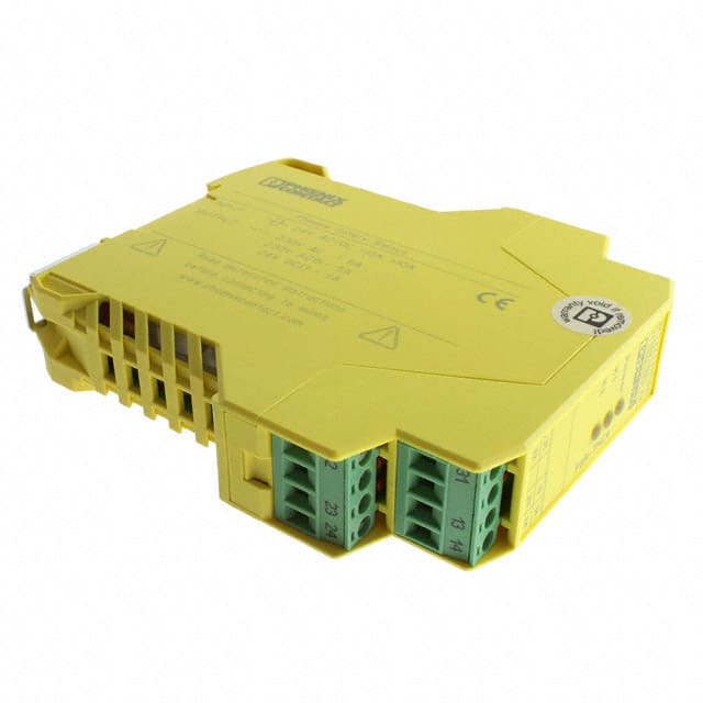
A safety relay is a crucial component in industrial and mechanical systems that helps ensure the safety of both people and machinery. It acts as a control device that monitors safety circuits and quickly responds to dangerous situations, such as equipment malfunctions or emergencies, by stopping or controlling processes to prevent accidents.
Safety relays are often connected to emergency stop buttons, safety sensors, or gates to trigger a safe response when a hazard is detected. Understanding how safety relays work and what factors make them activate is key to maintaining a safe working environment.

How does a safety relay work
The safety relay works by using electrical pulses through circuits to detect faults in contactors, actuators, and wiring. It has mechanically connected contacts, so when a normally open (NO) contact stays closed, the normally closed (NC) contact cannot close. The relay ensures contact groups are intact by measuring the current.
A safety relay is like a special "guardian" for machines in a factory. Its main job is to make sure the machine stops immediately if there's danger, to protect workers.
How does it know there's danger?
It needs to receive "alarm signals." These signals come from various safety devices, like:
- Emergency Stop Buttons: Like a big red button that says, "Stop the machine right now!" when someone presses it.
- Safety Gate Sensors: Placed on protective doors around machines. If a door opens, it knows someone might be entering a dangerous area.
- Light Curtains or Sensors: Set up around the machine. If a person breaks the light beam, it triggers an alarm.
When these safety devices detect a danger (like someone getting too close or the machine having a problem), they send an electrical signal to the safety relay.
What does the relay do when it gets the signal?
When the safety relay gets this signal, it immediately thinks, "Okay, there's danger! I need to act."
What's the difference between a safety relay and a regular relay?
Here's where it's really smart: A safety relay is designed to be extremely reliable, almost like having a double or even triple-check system inside.
It has backup parts: Even if one small part inside breaks, other backup parts make sure it can still work properly. It won't fail just because of one broken piece.
It checks itself: It's constantly checking to see if it is working correctly. If it finds a problem with itself, it might even stop the machine from starting or give a warning while running, making sure it's always ready for an emergency.
What happens once danger is confirmed?
When the safety relay receives the danger signal and its internal "judgment system" confirms that the machine needs to stop, it does one thing very, very quickly: it disconnects the electrical circuit that supplies power to the machine. Imagine someone instantly "pulling the power plug" on the machine.
By cutting off the power fast, the machine stops running immediately, which helps prevent accidents and keeps workers safe.
So, in simple terms, a safety relay relies on reliable safety devices to send "alarm signals." Then, using its super-reliable internal system, it judges the danger and, if confirmed, instantly "cuts off the power" to bring the machine to a safe stop. The more reliable the signals from the safety devices, the better the safety relay can do its job.

Okay, this text describes a typical safety relay circuit setup using three relays K1, K2, and K3 and their various connection points.
Here's a simplified explanation of how it works:
Circuit Setup:
- This setup acts like a complete safety relay unit.
- Safety sensors or devices connect between points A and B.
- A reset button connects between points C and D.
Points E and F are outputs, often connected to a controller (like a PLC) to show the safety relay's status whether the machine is allowed to run.
Points G and H are the main safety output, connected in the line that controls the final power switch (contactor) for the motor or machine.
The power supply for this circuit is probably around 110V.
How it Operates:
Starting State: When the power is first turned on, all three internal relays (K1, K2, K3) are off. The output terminals (E-F and G-H) are disconnected, so the machine cannot start.
Activating the Safety Relay:
- First, all safety devices must be in a safe state (their contacts between A and B must be closed). This allows power to reach points B and C.
- Then, you must press the reset button connecting C to D.
- Pressing the reset button allows power from C to flow to D, which turns on relay K3.
- When K3 turns on, it closes its contact, which in turn provides power to and activates relays K1 and K2.
- Crucially, K1 and K2 have a self-latching function. This means that once they turn on, they stay on using their own contacts, even if the signal from K3 or the reset button disappears.
After Reset: Once K1 and K2 are latched on, you can release the reset button. K3 will turn off, but K1 and K2 will remain on.
Outputs Engaged: With K1 and K2 on, the output terminals E-F and G-H become connected. E-F sends a "safe status" signal to the PLC, and G-H allows power to flow to the main motor contactor, so the machine can run.
Deactivating the Safety Relay:
- If any connected safety device is triggered (e.g., a safety gate is opened), its contacts between A and B will open.
- This immediately cuts power to point B, which in turn cuts power to relays K1 and K2.
- K1 and K2 turn off.
- When K1 and K2 turn off, they open the connections at terminals E-F and G-H.
- Opening G-H breaks the circuit to the main motor contactor, causing it to switch off and stop the motor immediately. E-F signals the PLC that the safety relay is now in a stop state.
Role of the Capacitor: A small capacitor is needed to ensure that K3 stays on for just a moment longer when you release the reset button. This slight delay gives K1 and K2 enough time to fully turn on and successfully latch themselves before K3 switches off.
Built-in Safety Design: Redundancy and Monitoring
Modern safety relays come with diagnostic features that continuously check the system’s components, including wiring, input signals, and internal circuits. These diagnostics are critical because they help identify problems before they cause system failure or unsafe conditions.
For example, a safety relay might have self-monitoring functions to detect wiring issues, signal disruptions, or component failures. If a problem is found, the relay can immediately issue a warning or even enter a safe state to stop the machinery from operating unsafely. Fault detection is especially important in industrial environments, where delays or failure to respond quickly can lead to costly damage or injuries.
The connection between diagnostic functions and the safety relay is crucial to ensuring safety. While the relay’s main job is to respond to emergency signals, its diagnostic features allow it to detect issues early on, so they can be addressed before they interfere with the system’s performance. This proactive monitoring ensures that the safety relay remains reliable and effective at all times.
Environmental Factors and Operating Conditions
Temperature is one of the most important environmental factors that affect how safety relays perform. At its core, temperature influences the materials and components inside the relay, which could alter their behavior and reliability.
Materials: Safety relays are made of materials like metals, plastics, and semiconductors, and each material has its own ideal temperature range. For example, conductive metals like copper can lose their ability to conduct electricity properly when exposed to high heat, leading to voltage drops or signal issues. Similarly, plastic parts can become brittle or soft if they experience extreme temperatures, which could lead to short circuits or damage to the relay.
Electrical Components: Inside the safety relay, components like resistors, capacitors, and transistors can also be affected by temperature changes. For instance, resistors may change their resistance as temperature increases or decreases, which can cause incorrect readings or signals. Semiconductor parts, such as transistors, may also change their properties due to temperature shifts, affecting the relay’s ability to process input signals or control outputs.
Thermal Expansion and Contraction: Temperature fluctuations can cause physical expansion or contraction of the components inside the relay. For example, metal contacts or wiring inside the relay may expand in high temperatures and contract in low temperatures. Over time, these temperature changes can cause poor connections, increase wear on components, or even cause the relay to fail if the mechanical stress becomes too high.
Response Times: Extreme temperatures can also affect how quickly the safety relay responds. At high temperatures, certain components inside the relay may work slower, delaying the relay’s response to input signals. On the other hand, very low temperatures may cause some components to become sluggish or fail entirely.
Ambient Temperature: The temperature around the relay (ambient temperature) is also crucial for determining its operational environment. A relay meant for high-temperature conditions, like those in manufacturing or outdoor settings, must be designed to handle such environments. Conversely, relays made for controlled environments, such as cleanrooms or office buildings, will be less rugged and may fail if exposed to extreme heat or cold.
Why Temperature Matters for Safety
The main concern with temperature changes is that they can affect the safety relay’s reliability and accuracy. Safety relays are meant to respond quickly in emergencies, and if temperature fluctuations cause them to malfunction, they might not react as needed, which could delay a response or cause the relay to fail to activate. This is why relays used in critical safety applications must be rated for the temperature conditions they will face and undergo extensive testing to ensure they can function safely in various environments.
Time Delay Mechanisms for Controlled Response
Time delay mechanisms in safety relays introduce a brief pause before the relay activates a response. These delays are important in situations where an immediate shutdown or activation might not be necessary or could cause more harm than good. By adding a short delay, the system ensures the relay responds in a controlled way, preventing potential damage to machinery or equipment.
Why Time Delays Are Needed
Preventing False Triggers: Sometimes, external factors like electrical noise, sensor reading delays, or temporary interruptions can cause slight changes in input signals. Without a time delay, these minor fluctuations could cause the safety relay to trigger a response unnecessarily, leading to unwanted shutdowns or system resets. The time delay helps avoid these false triggers by ensuring the relay only activates when there’s a real emergency or unsafe condition.
Safe Machine Operation: In systems with large machinery or heavy equipment, an abrupt stop or start can cause mechanical stress or damage. For example, if the relay immediately stops a conveyor belt or motor, it could damage parts like gears or belts, or even create safety risks for workers. A time delay allows the system to gradually stop or start machinery, reducing the shock load and ensuring smoother, safer operations.
Coordinating Multiple Relays: In complex systems with several safety relays, time delays can help coordinate their activation. For example, in systems that require a specific sequence of shutdown steps, the delay ensures that relays trigger in the right order. This is especially important in systems where the safety of one part depends on the shutdown of other parts, such as in automated production lines or industrial robots.
How Time Delays Work in Safety Relays
Time delays in safety relays usually involve adjustable timers that can be set to a particular duration. When the relay receives an input signal (like from an emergency stop or sensor alarm), it holds off on responding for the programmed time. During this delay, the relay checks the signals again to make sure the condition still requires action. If the danger persists, the relay will then trigger the appropriate response, like stopping the system or activating a backup.
In some cases, on-delay timers are used, where the relay waits for a certain time before activating after receiving a signal. Off-delay timers are used in other cases, where the relay keeps the system running for a set period even after the signal stops, ensuring a smooth transition or delayed response.
For example, if an emergency stop button is pressed to stop a conveyor belt, without a time delay, the relay would immediately stop the conveyor, which could cause mechanical damage. With a time delay, the safety relay can introduce a brief pause, allowing the conveyor to slow down gradually before it stops. This controlled shutdown prevents mechanical damage and ensures the system stops safely.
Conclusion
Safety relays are essential for protecting both people and machinery by quickly responding to emergency signals. The main factors that allow them to work properly include input signals from safety devices, reliable wiring, and a steady power supply. Internal redundant circuits and diagnostic features increase their reliability, while time delay mechanisms help the system respond smoothly without causing disruptions. Understanding how these factors interact helps ensure that safety relays provide effective protection in industrial systems.